Suzuki Access 125 Engine Diagram
Volkswagen Jetta 6 (2011 – 2016) – fuse box diagram
Year of production: 2011, 2012, 2013, 2014, 2015, 2016
Engine compartment
The under-hood fuse box is located in the engine compartment on the driver's side.
| Fuse name | [A] | Circuit protected |
| R1 | — | — |
| R2 | — | — |
| R3 | — | — |
| R4 | — | — |
| R5 | — | — |
| R6 | — | — |
| F1 | 10/15 | Engine management |
| F2 | 5 | Engine coolant blower motor |
| F3 | 5 | Engine coolant blower motor |
| F4 | 5/10/15 | Engine management |
| F5 | 5/10/20 | |
| F6 | 5/10/15 | |
| F7 | 5/20 | Engine management |
| F8 | 10 | Engine management |
| F9 | 5/15 | |
| F10 | 5 | |
| F11 | — | — |
| F12 | 5/20 | |
| F13 | 5 | |
| F14 | 5 | Engine management |
| F15 | 30 | Voltage stabilizer module |
| F16 | 30 | ABS/ESP system |
| F17 | 30 | Transmission |
| F18 | 20 | Transmission |
| F19 | 1 | Multifunction control module |
| F20 | 30 | |
| F21 | 50 | Secondary air injection (AIR)pump |
| F22 | — | — |
| F23 | 40 | ABS/ESP system |
| F24 | 50 | Trailer control module |
| F25 | 50 | Ignition main circuits |
| F26 | 60 | Glow plugs |
| F27 | 60 | Engine coolant blower motor |
| F28 | 40 | Multifunction control module |
| F29 | 40 | Multifunction control module |
| F30 | 50 | Ignition auxiliary circuits |
| F31 | 30 | Audio unit output amplifier |
| F32 | 40 | Engine coolant heater |
| F33 | — | — |
| F34 | 200 | Alternator |
| F35 | — | — |
| F36 | 80 | Power steering |
| F37 | 80 |
Passenger compartment
The interior fuse box is underneath the steering column.
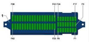
Codes as follows (2011)
| Fuse name | [A] | Circuit protected |
| F1 | — | — |
| F2 | 5 | Steering column lock |
| F3 | 10 | Instrument panel |
| F4 | — | — |
| F5 | — | — |
| F6 | 10 | Multifunction control module |
| F7 | 5 | |
| F8 | 7,5 | |
| F9 | 5 | Supplementary restraint system (SRS) |
| F10 | 10 | |
| F11 | — | — |
| F12 | — | — |
| F13 | 5 | |
| F14 | 10 | |
| F15 | 10 | |
| F16 | 10 | Engine management |
| F17 | — | — |
| F18 | 15 | LH headlamp |
| F19 | 15 | RH headlamp |
| F20 | 10 | |
| F21 | — | — |
| F22 | 10 | |
| F23 | 10 | |
| F24 | 10 | |
| F25 | 15 | Transmission |
| F26 | 15 | Brake servo vacuum pump |
| F27 | — | — |
| F28 | 40 | Engine coolant heater |
| F29 | 1 | Multifunction control module |
| F30 | 20 | Cigarette lighter, 12 V socket, 12 V socket 2, Blocking diode |
| F31 | 30 | Light switch |
| F32 | 30 | Light switch |
| F33 | 40 | |
| F34 | 15 | |
| F35 | 10 | |
| F36 | 25 | Multifunction control module |
| F37 | 15 | LH headlamp |
| F38 | 15 | RH headlamp |
| F39 | 15 | Headlamp low beam |
| F40 | 15 | Trailer control module |
| F41 | 15 | Trailer control module |
| F42 | 20 | Trailer control module |
| F43 | 30 | Door function control module, passenger |
| F44 | 25 | |
| F45 | 25 | |
| F46 | 25 | |
| F47 | 15 | Fuel pump(FP) |
| F48 | 20 | Multifunction control module |
| F49 | 40 | AC/heater system |
| F50 | 30 | Heated seats |
| F51 | 20 | Sunroof |
| F52 | 20 | Horn |
| F53 | 15 | Heated seats |
| F54 | 15 | Rear fog lamps |
| F55 | 20 | |
| F56 | — | — |
| F57 | 15 | Audio unit/navigation system |
| F58 | 1/30 | |
| F59 | 30 | Audio unit output amplifier |
| F60 | 30 | Engine coolant heater |
codes as follows (since 2012)
| Fuse name | [A] | Circuit protected |
| F1 | — | — |
| F2 | 5/7,5 | Steering column lock |
| F3 | 10 | Instrument panel |
| F4 | 2/10 | Telephone transceiver, Compass magnetic field sensor, stabilized |
| F5 | 7,5 | LH rear fog lamp |
| F6 | 10 | Multifunction control module |
| F7 | 5 | Fog lamp relay |
| F8 | 7,5 | Windshield and headlamp washer pump switch, Windshield washer pump |
| F9 | 5 | Supplementary restraint system (SRS) |
| F10 | 10 | Right steering column switch |
| F11 | — | — |
| F12 | — | — |
| F13 | 5 | Automatic dimming interior rearview mirror, Light recognition sensor, Parking aid control module, Air quality sensor, High pressure sensor, Climatronic control unit, Tire pressure monitoring button, ASR/ESP button, Back-up lamp switch, Start/Stop mode switch, Left washer nozzle heater, Right washer nozzle heater, 28-pin connector, Mirror adjusting switch, Exterior rearview mirror heating switch, Cornering lamp and headlamp range control module |
| F14 | 10 | Left steering column switch, ABS control module, Light switch, Airbag spiral spring/return spring with slip ring, Fuel pump control module, Towing recognition control module, Voltage stabilizer, Converter with socket, Data bus on board diagnostic interface |
| F15 | 10 | 16-pin connector -T16- , (diagnostic connector), Instrument panel and switch illumination dimmer switch, Headlamp range control adjuster -E102- , Fresh air blower relay, Mass airflow sensor, Positive crankcase ventilation heating element, Structure borne sound control module, Left front headlamp, Left headlamp beam adjustment motor, Right front headlamp, Right headlamp beam adjustment motor |
| F16 | 10 | Auxiliary coolant pump relay, Engine control module |
| F17 | — | Alarm system |
| F18 | 15 | LH headlamp |
| F19 | 15 | RH headlamp |
| F20 | 10 | Ignition/starter switch, Tiptronic switch, Automatic transmission control module, Selector lever sensor system control module, Climatronic control unit, Auxiliary engine coolant heater radio frequency receiver |
| F21 | 15/20 | Vehicle electrical system control module, Dual tone horn relay, High tone horn, Low tone horn |
| F22 | 7,5/20 | Ignition/starter switch, Converter box, Interior monitoring sensor, Alarm horn relay, Alarm horn |
| F23 | 10 | Vehicle electrical system control module, 16-pin connector, (diagnostic connector) Light switch, Rain/light recognition sensor, Compass magnetic field sensor |
| F24 | 10 | Vehicle electrical system control module, Access/start authorization control module |
| F25 | 15 | Transmission |
| F26 | 15 | Brake servo vacuum pump |
| F27 | 1 | Supplementary restraint system (SRS) |
| F28 | 40 | Engine coolant heater |
| F29 | 1 | Multifunction control module |
| F30 | 20 | Cigarette lighter, 12 V socket, 12 V socket 2, Blocking diode |
| F31 | 30 | Light switch |
| F32 | 30 | Light switch |
| F33 | 40 | Heater/heat output switch, Fresh air blower relay, A/C control module, Fresh air blower switch |
| F34 | 15 | Left high beam headlamp bulb, Right high beam headlamp bulb, Instrument cluster control module |
| F35 | 10 | Steering column electronics control module, Data bus on board diagnostic interface, Signal horn activation |
| F36 | 25 | Multifunction control module |
| F37 | 15 | Left front headlamp, Left daytime running lamp bulb |
| F38 | 15 | Right front headlamp, Right daytime running lamp bulb |
| F39 | 15 | Headlamp low beam |
| F40 | 15 | Trailer control module |
| F41 | 15 | Trailer control module |
| F42 | 20 | Trailer control module |
| F43 | 30 | Door function control module, passenger |
| F44 | 25 | Rear window defogger relay, Rear window defogger, Vehicle electrical system control module |
| F45 | 25 | Driver door control module, Front passenger door control module |
| F46 | 25 | Left rear door control module, Right rear door control module |
| F47 | 15 | Fuel pump(FP) |
| F48 | 20 | Multifunction control module |
| F49 | 40 | AC/heater system |
| F50 | 30 | Heated seats |
| F51 | 20 | Sunroof |
| F52 | 20 | Horn |
| F53 | 15 | Heated seats |
| F54 | 15 | Rear fog lamps |
| F55 | 20 | Light switch, Left steering column switch |
| F56 | — | — |
| F57 | 15/25 | Audio unit/navigation system |
| F58 | 30 | Accessories connector |
| F59 | 30 | Audio unit output amplifier |
| F60 | 30 | Engine coolant heater |
Relay box fascia 2 (2011 Volkswagen Jetta)
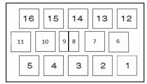
| Relay | Circuit protected |
| 1 | Ignition switch control module |
| 2 | |
| 3 | |
| 4 | |
| 5 | Headlamp dim-dip relay |
| 6 | |
| 7 | Ignition auxiliary circuits relay |
| 8 | Horn relay |
| 9 | Headlamp washer pump relay |
| 10 | |
| 11 | |
| 12 | Heated rear window relay |
| 13 | |
| 14 | |
| 15 | |
| 16 | Fog lamp relay |
Relay box fascia 2 (2012 Volkswagen Jetta)
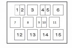
| Relay | Circuit protected |
| 1 | Horn relay |
| 2 | Headlamp washer pump relay |
| 3 | |
| 4 | |
| 5 | |
| 6 | |
| 7 | Ignition auxiliary circuits relay |
| 8 | |
| 9 | |
| 10 | Auxiliary heater relay |
| 11 | |
| 12 | |
| 13 | |
| 14 | |
| 15 | Ignition switch control module |
Relay box fascia 2 (2013 Volkswagen Jetta)
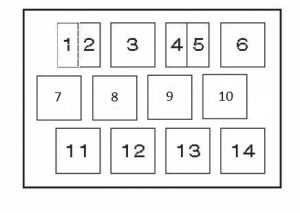
| Relay | Circuit protected |
| 1 | |
| 2 | |
| 3 | |
| 4 | |
| 5 | |
| 6 | |
| 7 | |
| 8 | |
| 9 | |
| 10 | |
| 11 | |
| 12 | Ignition auxiliary circuits relay |
| 13 | |
| 14 | Ignition switch control module |
Location of electronic components
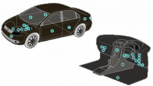
| Number | Component |
| 1 | ABS control module |
| 2 | AC control module |
| 3 | Battery |
| 4 | Data link connector (DLC) |
| 5 | Diagnostic module |
| 6 | Door function control module, driver |
| 7 | Door function control module, left rear |
| 8 | Door function control module, passenger |
| 9 | Door function control module, right rear |
| 10 | Engine control module(ECM) |
| 11 | Fuse box/relay plate, engine bay |
| 12 | Fuse box/relay plate, fascia 1 |
| 13 | Fuse box/relay plate, fascia 2 |
| 14 | Glow plug control module-under engine bay fuse box/relay plate |
| 15 | Headlamp level control module |
| 16 | Heater blower speed resistor-near heater blower motor |
| 17 | Horn |
| 18 | Ignition switch control module (some models) – in fascia fuse box/relay plate 2 |
| 19 | Keyless entry/start control module |
| 20 | Multifunction control module-functions: Alarm system , central locking, charging system , door function control modules, electrical load control, exterior lamps, footwall lamps , fuel filler flap release, fuel pump (FP), heated door mirrors , heated rear window, horn , immobilizer, indicators/hazard warning lamps, instrument illumination , interior lamps, keyless entry/start system, rain/ambient light sensor, stop lamps ,wind screen wash/wipe system |
| 21 | Parking aid control module |
| 22 | Power steering control module-on steering rack |
| 23 | Seat heater control module-under driver's seat |
| 24 | Steering column function control module |
| 25 | Steering column lock control module |
| 26 | Supplementary restraint system (SRS) control module |
| 27 | Trailer control module- LH luggage compartment |
| 28 | Transmission control module (TCM) (DSG transmission) |
| 29 | Transmission control module(TCM) – with AT |
WARNING: Terminal and harness assignments for individual connectors will vary depending on vehicle equipment level, model, and market.
Source: https://www.autogenius.info/volkswagen-jetta-6-2011-2016-fuse-box-diagram/
Posted by: kennithkennithfragae0270609.blogspot.com
Post a Comment for "Suzuki Access 125 Engine Diagram"